The latest version
of the 4 axis driver board TA8435 for stepper motor
This one is with
the heatsink and the parallel cable
Here are the comparison of the old version and this new version. We have done some modifications on this new board.
|
|
Old version |
V8 new version |
comparisons |
advantages |
|
1 |
4 axis |
4 axis |
same |
|
|
2 |
The 5th axis adopts the pin
connection |
The 5th axis adopts the DB9
standard port |
modification |
Convenient and stable |
|
3 |
Standard Parallel port |
Standard Parallel port |
same |
|
|
4 |
the parallel protection adopts the common
optical coupler PC817 |
the parallel protection adopts the |
modification |
More stable and no-lost-step |
|
5 |
Main axis relay control output |
Main axis relay control output |
same |
|
|
6 |
High voltage and low voltage hybrid routing |
High voltage and low voltage seperated routing |
modification |
More stable |
|
7 |
1,2,1/4,1/8 four resolution choices |
1,2,1/4,1/8 four resolution choices |
same |
|
|
8 |
5V, 12-36 double power input |
12-36V single power input adopts the Chip
as the 5V power, more stable and less heat |
modification |
Stable and easy to connect |
|
9 |
555 semi-flow |
RC+7414 auto semi-flow |
modification |
Reduce the interference |
|
10 |
No fan port |
5V fan port |
modification |
External fan |
1、The definition of the 25 paraller control
pins:
|
PIN1 |
PIN2 |
PIN3 |
PIN4 |
PIN5 |
PIN6 |
PIN7 |
PIN8 |
PIN9 |
PIN10 |
|
CKE |
CKA |
CWA |
CKB |
CWB |
CKC |
CWC |
CKD |
CWD |
DIN1 |
|
E axis
pulse |
A axis
pulse |
A axis direction |
B axis
pulse |
B axis direction |
C axis
pulse |
C axis direction |
D axis
pulse |
D axis direction |
Limit 1 |
|
PIN11 |
PIN12 |
PIN13 |
PIN14 |
PIN16 |
PIN17 |
PIN18~25 |
|
|
|
|
DIN2 |
DIN3 |
DIN4 |
CWE |
EN |
RLY |
GND |
|
|
|
|
Limit 2 |
Limit 3 |
Limit 4 |
E axis direction |
All
axis can use |
Relay
control |
GND |
|
|
|
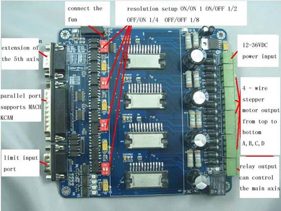
2、Please take power 12 ~ 24V
3、5th axis extension ,the JP1 is the extension port of the 5th
axis, DB9 D1-EN+ D6-EN- D2-DIR+
D7-DIR- D3-STEP+ D8-STEP-
4、The definition of limit
input:DB9 (1-6) Corresponding to the PC parallel port P13
DB9 (2-7) Coresponding
to the parallel port P12 DB9 (3-8)----
P 11 DB9 (4-9)----P10
The resolution setup
S2/S1 ON/ON non resolution ON/OFF
1/2 OFF/ON 1/4 OFF/OFF 1/8
How to use the MACH3 software.
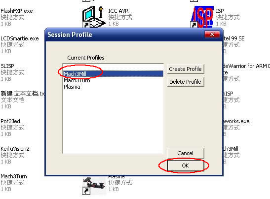
图1
Fig1:
open the mach3 software , choose the mach3 MILL
---choose ok.
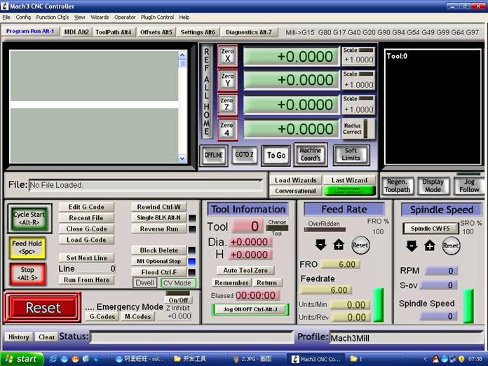
图2
Fig2:
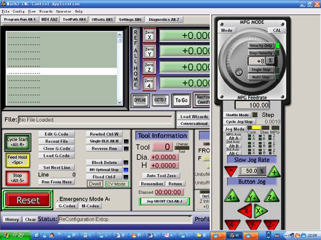
we deploy the mach3 software.
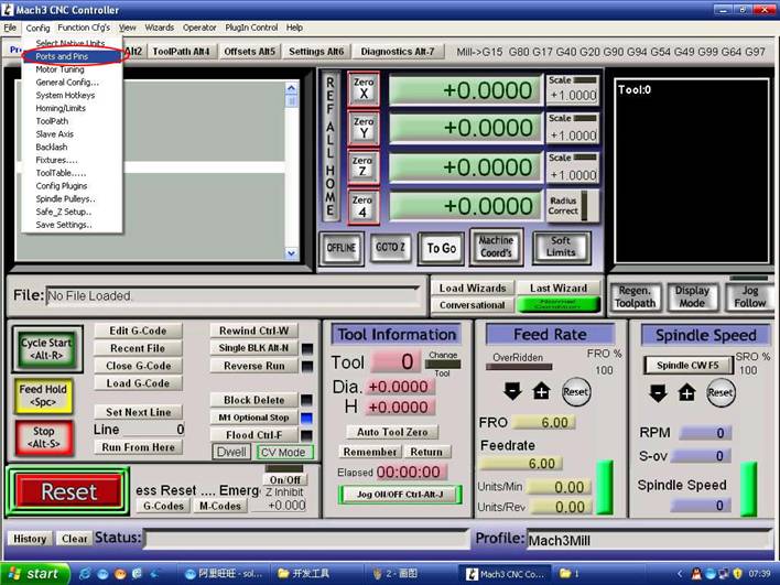
图3
Fig3:
open the port and pin menu under the config
menu.
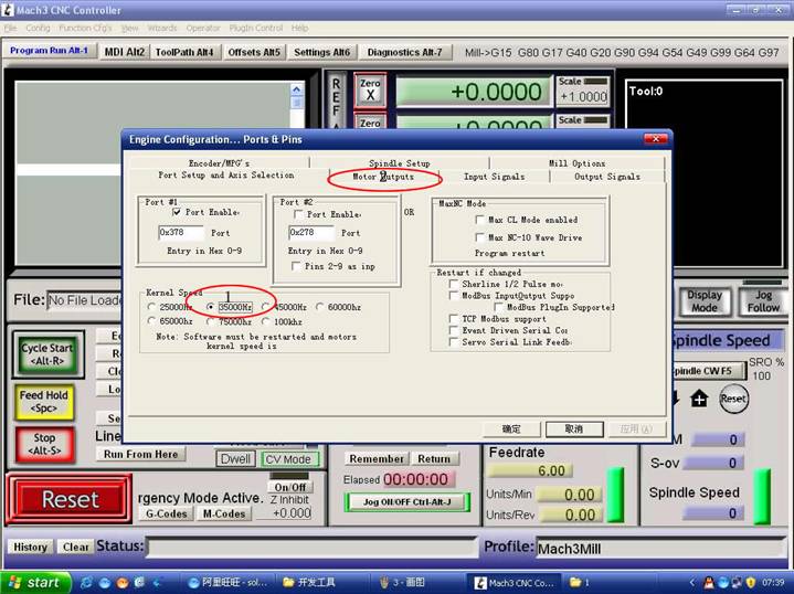
图4
Fig4:set the standard frenquency in
the first circle , this data influence the speed of the motor , and then choose
the definition in the second circle to set up the pin.
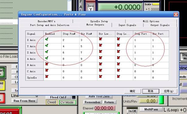
图5
Fig5:follow the circle in the figure to set the software.
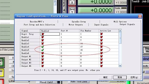
图6
Fig6:choose the output signals , follow the circle in the figure
to set .
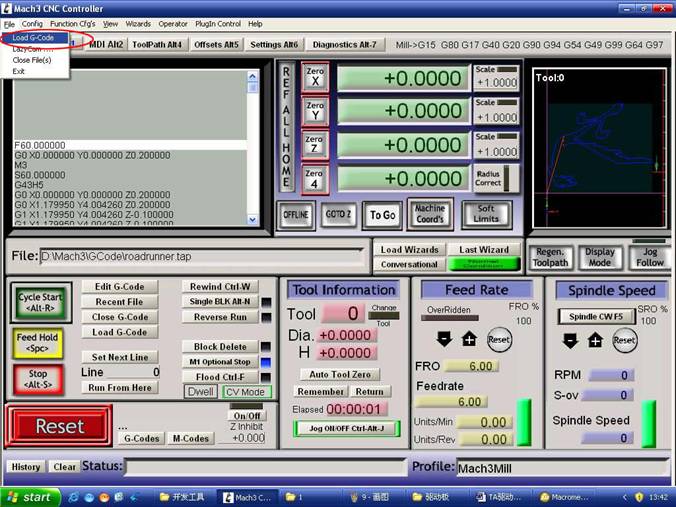
图7
Fig7:
choose ok and the open the G code that we need to run.
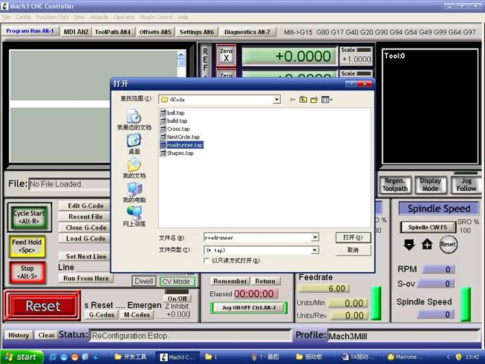
图8
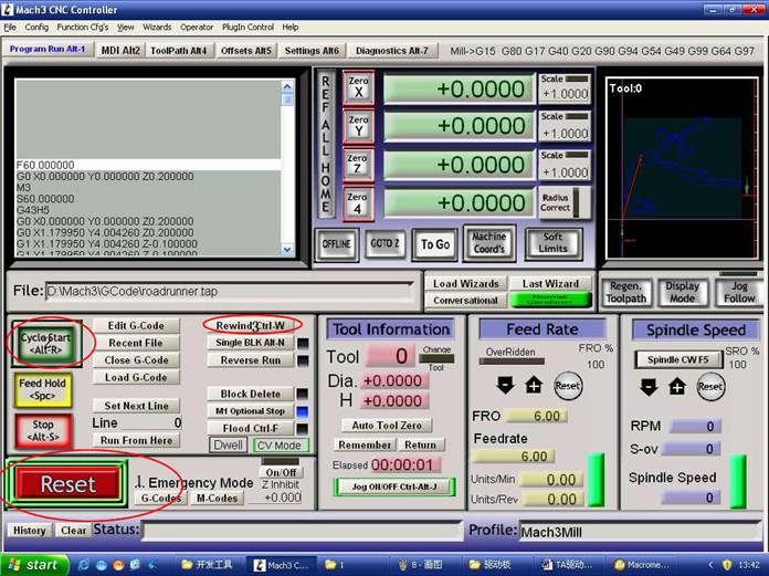
图9
Fig8:after opening the G code , you will see the red reset ,
click it and then run the cyclestart.
If
need the manuel control ,
you can use the TAB to control it .